PIC ile DC motor yön ve hız kontrolü

Öncelikle herkese iyi akşam benim sorunum PIC16F877 proteus ortamında oluşturduğum resimde görülen devrenin

DC motorun hız ve yön kontrolünü yapmaya çalıştırğımda herhangi bir tepki alamıyorum. Bu konuda bana yardımcı olur musunuz şimdiden teşekkürler herkese.
Kod dosyası ise şu şekildedir:

#include <16f877.h>
#device adc=8
#use delay(clock=4000000)
#fuses XT,NOWDT,NOPUT,NOLVP,NOCPD,NOPROTECT,NODEBUG,NOBROWNOUT,NOWRT

#use fast_io(a)
#use fast_io(b)
#use fast_io(c)

#define ileri pin_a0
#define geri  pin_a1
#define dur   pin_a2
#define input1 pin_b0
#define input2 pin_b1
#define enable_a pin_b2
#define enable_b pin_b3

#define use_portb_lcd TRUE
#include <lcd.c>

unsigned int deger;
float voltaj;

void main()
{
   setup_psp(PSP_DISABLED);
   setup_timer_1(T1_DISABLED);
   setup_timer_2(T2_DISABLED,0,1);
   setup_adc_ports(NO_ANALOGS);
   setup_adc(ADC_OFF);
   setup_CCP1(CCP_OFF);
   setup_CCP2(CCP_OFF);
   setup_psp(PSP_DISABLED);
   setup_timer_1(T1_DISABLED);
   setup_timer_2(T2_DIV_BY_4,255,1);

   
   setup_CCP1(CCP_PWM);
   setup_CCP2(CCP_OFF);
   
   setup_adc(adc_clock_div_32);
   setup_adc_ports(ALL_ANALOG);
   
   set_tris_a(0x07); //0b 0000 0111
   set_tris_b(0x00);  
   set_tris_a(0x20);
   set_tris_b(0x00);
   set_tris_c(0x20);
   
   output_high(enable_a);
   output_low(enable_b);   
   
   set_adc_channel(4);
   delay_us(20);
   
   output_c(0x00);
   lcd_init();
   printf(lcd_putc,"\fAhmet KULABAS\nB200101044");
   delay_ms(1000);
   
   set_pwm1_duty(0);
   
   while(true){
   if(input(ileri)){
   output_high(pin_c3);
   output_low(pin_c4);
   }
   else if(input(geri)){
   output_low(pin_c3);
   output_high(pin_c4);
   }
   else if(input(dur)){
   output_low(pin_c3);
   output_low(pin_c4);
   }
      
   
   deger=read_adc();
   delay_us(20);
   voltaj=deger/51.0;
  

 /*
   output_high(pin_c3);
   output_low(pin_c4);
 */ 
   set_pwm1_duty(deger);
   
   printf(lcd_putc,"\fVoltaj=%f V",voltaj);
   lcd_gotoxy(1,2);
   printf(lcd_putc,"Deger=%u",deger);
   delay_ms(1000);

   
   }


   }

Analog okumayı A0 ile yapınız. Zira diğer PORTA
pinleri de analog giriş olur.
PIC16F877 ADCON1 kaydedicisinin açıklamasına
bakınız.

Asıl hata L298 kontrol pinlerinde:
kodunuzda; B0 ve B1 pinleri kullanılmış, ancak şemada
C3 ve C4 olarak bağlanmış.

CCS C bilmiyorum. MPLABX IDE ile yardımcı olabilirim.

EK:
L298 akım sınırlama dirençlerinin değerini de düşürün.

O pinleri LCD ekran için kullanıyorum.
C3 ve C4 numaralı pinleri aşağıdaki kod satırında çıkış pinleri olarak kullanıyorum.

 if(input(ileri)){
   output_high(pin_c3);
   output_low(pin_c4);
   }
   else if(input(geri)){
   output_low(pin_c3);
   output_high(pin_c4);
   }
   else if(input(dur)){
   output_low(pin_c3);
   output_low(pin_c4);
   }

Peki MPLABX IDE ile nasıl düzeltilir. o konuda yardımcı olur musunuz olmadı MPLABX IDE bunla yazmayı denerim

Sadece motor mu çalışmıyor?

Evet sadece motor çalışmıyor hiç bir türlü 2 sini ayrı ayrı yapınca çalışıyor bir arada yapınca çalışmıyor

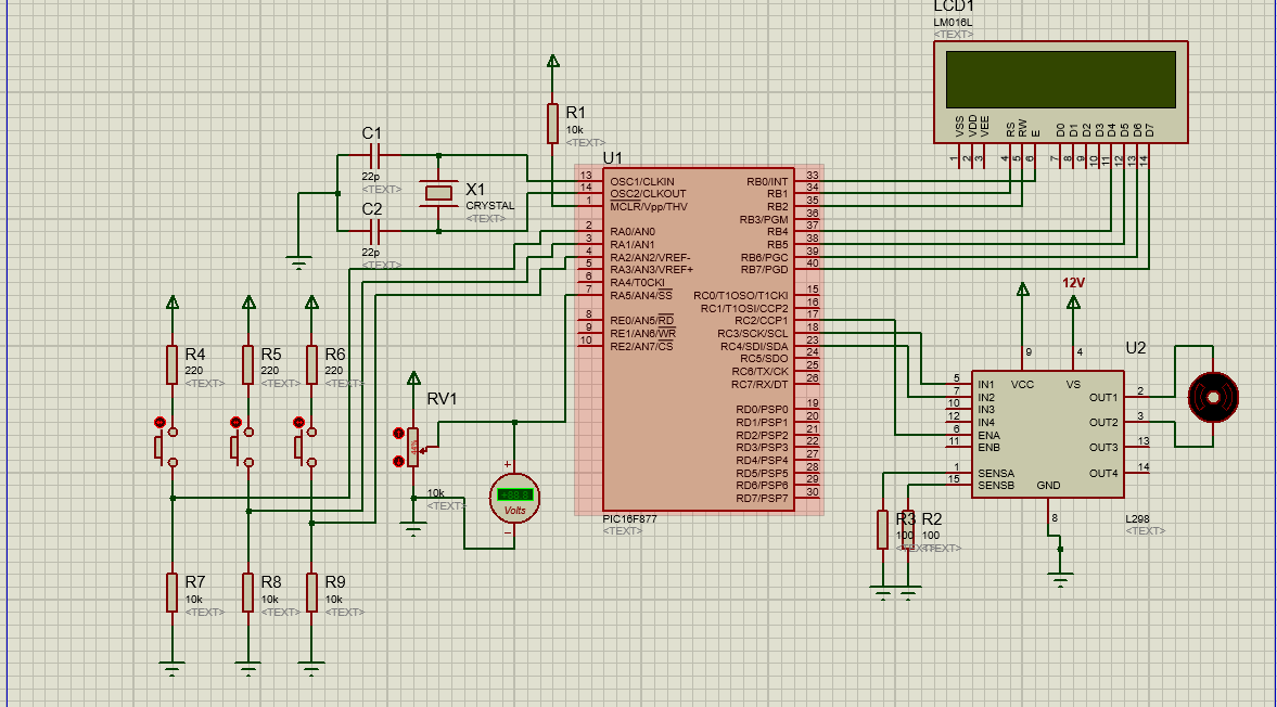
Bunu deneyin. Butonları simülasyonda A1, A2, A3 ve
pot girişini A0 olarak değiştirin.
Olmazsa, altta MPLABX için kodu da ekledim.

#include <16f877.h>
#device adc=8
#use delay(clock=4000000)
#fuses XT,NOWDT,NOPUT,NOLVP,NOCPD,NOPROTECT,NODEBUG,NOBROWNOUT,NOWRT

#use fast_io(a)
#use fast_io(b)
#use fast_io(c)

/*#define ileri pin_a0
#define geri  pin_a1
#define dur   pin_a2*/

#define ileri pin_a1
#define geri  pin_a2
#define dur   pin_a3

//#define input1 pin_b0
//#define input2 pin_b1
//#define enable_a pin_b2
//#define enable_b pin_b3

#define use_portb_lcd TRUE
#include <lcd.c>

unsigned int deger;
float voltaj;

void main()
{
   setup_psp(PSP_DISABLED);
   setup_timer_1(T1_DISABLED);
   setup_timer_2(T2_DISABLED,0,1);
   setup_adc_ports(NO_ANALOGS);
   setup_adc(ADC_OFF);
   setup_CCP1(CCP_OFF);
   setup_CCP2(CCP_OFF);
   setup_psp(PSP_DISABLED);
   setup_timer_1(T1_DISABLED);
   setup_timer_2(T2_DIV_BY_4,255,1);

   
   setup_CCP1(CCP_PWM);
   setup_CCP2(CCP_OFF);
   
   setup_adc_ports(RA0_ANALOG); 	
   setup_adc(adc_clock_div_32);
   //setup_adc_ports(ALL_ANALOG);
   
   set_tris_a(0x07); //0b 0000 0111
   set_tris_b(0x00);  
   set_tris_a(0x20);
   set_tris_b(0x00);
   set_tris_c(0x20);
   
   //output_high(enable_a);
   //output_low(enable_b);   
   
   //set_adc_channel(4);
   set_adc_channel(0);
   delay_us(20);
   
   output_c(0x00);
   lcd_init();
   printf(lcd_putc,"\fAhmet KULABAS\nB200101044");
   delay_ms(1000);
   
   set_pwm1_duty(0);
   
   while(true)
   {
	   if(input(ileri))
	   {
	   	 output_high(pin_c3);
		 output_low(pin_c4);
	   }
	   else if(input(geri))
	   {
		 output_low(pin_c3);
		 output_high(pin_c4);
	   }
	   else if(input(dur))
	   {
		 output_low(pin_c3);
		 output_low(pin_c4);
	   }     
	   
	   deger = read_adc();
	   delay_us(20);
	   voltaj = deger/51.0;	  

	 /*
	   output_high(pin_c3);
	   output_low(pin_c4);
	 */ 
	   
	   set_pwm1_duty(deger);
	  
	   printf(lcd_putc,"\fVoltaj=%f V",voltaj);
	   lcd_gotoxy(1,2);
	   printf(lcd_putc,"Deger=%u",deger);
	   delay_ms(1000);   
   }
}

MPLABX için:
lcd.h


//LCD Functions Developed by electroSome

//------------------------------------------------------------------------------
//

void Lcd_Port(char a)
{
    if (a & 1)
        D4 = 1;
    else
        D4 = 0;

    if (a & 2)
        D5 = 1;
    else
        D5 = 0;

    if (a & 4)
        D6 = 1;
    else
        D6 = 0;

    if (a & 8)
        D7 = 1;
    else
        D7 = 0;
}

//------------------------------------------------------------------------------
//

void Lcd_Cmd(char a)
{
    RS = 0; // => RS = 0
    Lcd_Port(a);
    EN = 1; // => E = 1
    __delay_ms(4);
    EN = 0; // => E = 0
}

//------------------------------------------------------------------------------
//

Lcd_Clear(void)
{
    Lcd_Cmd(0);
    Lcd_Cmd(1);
}

//------------------------------------------------------------------------------
//

void Lcd_Set_Cursor(char a, char b)
{
    char temp, z, y;
    if (a == 1)
    {
        temp = 0x80 + b - 1;
        z = temp >> 4;
        y = temp & 0x0F;
        Lcd_Cmd(z);
        Lcd_Cmd(y);
    }
    else if (a == 2)
    {
        temp = 0xC0 + b - 1;
        z = temp >> 4;
        y = temp & 0x0F;
        Lcd_Cmd(z);
        Lcd_Cmd(y);
    }
}

//------------------------------------------------------------------------------
//

void Lcd_Init(void)
{
    Lcd_Port(0x00);
    __delay_ms(20);
    Lcd_Cmd(0x03);
    __delay_ms(5);
    Lcd_Cmd(0x03);
    __delay_ms(11);
    Lcd_Cmd(0x03);
    /////////////////////////////////////////////////////
    Lcd_Cmd(0x02);
    Lcd_Cmd(0x02);
    Lcd_Cmd(0x08);
    Lcd_Cmd(0x00);
    Lcd_Cmd(0x0C);
    Lcd_Cmd(0x00);
    Lcd_Cmd(0x06);
}

//------------------------------------------------------------------------------
//

void Lcd_Write_Char(char a)
{
    char temp, y;
    temp = a & 0x0F;
    y = a & 0xF0;
    RS = 1; // => RS = 1
    Lcd_Port(y >> 4); //Data transfer
    EN = 1;
    __delay_us(40);
    EN = 0;
    Lcd_Port(temp);
    EN = 1;
    __delay_us(40);
    EN = 0;
}

//------------------------------------------------------------------------------
//

void Lcd_Write_String(const char *a)
{
    int i;
    for (i = 0; a[i] != '\0'; i++)
        Lcd_Write_Char(a[i]);
}

//------------------------------------------------------------------------------
//

void Lcd_Shift_Right(void)
{
    Lcd_Cmd(0x01);
    Lcd_Cmd(0x0C);
}

//------------------------------------------------------------------------------
//

void Lcd_Shift_Left(void)
{
    Lcd_Cmd(0x01);
    Lcd_Cmd(0x08);
}

//******************************************************************************

main.c

#include <stdio.h>
#include <stdlib.h>
#include <stdint.h>
#include <string.h>
#include <xc.h>

// #pragma config statements should precede project file includes.
// Use project enums instead of #define for ON and OFF.

// CONFIG
#pragma config FOSC  = HS        // Oscillator Selection bits (HS oscillator)
#pragma config WDTE  = OFF       // Watchdog Timer Enable bit (WDT disabled)
#pragma config PWRTE = ON       // Power-up Timer Enable bit (PWRT enabled)
#pragma config BOREN = ON       // Brown-out Reset Enable bit (BOR enabled)
#pragma config LVP   = OFF        // Low-Voltage (Single-Supply) In-Circuit Serial Programming Enable bit (RB3 is digital I/O, HV on MCLR must be used for programming)
#pragma config CPD   = OFF        // Data EEPROM Memory Code Protection bit (Data EEPROM code protection off)
#pragma config WRT   = OFF        // Flash Program Memory Write Enable bits (Write protection off; all program memory may be written to by EECON control)
#pragma config CP    = ON          // Flash Program Memory Code Protection bit (All program memory code-protected)


#define _XTAL_FREQ 4000000

#define RS PORTBbits.RB0    //RD2
#define EN PORTBbits.RB1    //RD3
#define D4 PORTBbits.RB4    //RD4
#define D5 PORTBbits.RB5    //RD5
#define D6 PORTBbits.RB6    //RD6
#define D7 PORTBbits.RB7    //RD7

#include "lcd.h" // LCD kütüphanesi çağrılıyor

#define ileri           PORTAbits.RA1
#define geri            PORTAbits.RA2
#define dur             PORTAbits.RA3

#define input1          PORTCbits.RC3
#define input2          PORTCbits.RC4

const char mb[] = "  Mehmet Bilgi";


/*
 * Project name:
 *    BJD_PWM_Functions
 * Author:
 *    Barton J.  Dring 08/2007
 * Description:
 *    This code demonstrates some PWM functions
 * Test configuration:
 *   MCU:             PIC16F877A
 *    Dev.Board:       EasyPIC4
 *    Oscillator:      HS, 08.0000 MHz
 *    Ext. Modules:    LCD
 *    SW:              mikroC v6.0
 * NOTES:
 *    None.
 */

/*
 * ================ setPWMDuty ==================================================
 *
 * This sets the registers for the PWM duty.  This is a maximum of a 10-bit value,
 * but many PWM settings will limit this anount.
 *
 * Parameters:
 *    duty:   The duty value to set in the register.  This is the actual value,
 *            not a percent.
 *
 * Returns:
 *    none:
 *
 * =============================================================================
 */
void setPWMDuty(unsigned int duty)
{
    CCPR1L = duty >> 2; // Set MSB values
    CCP1CON = ((duty & 3) << 4) | 0x0C; // set initial duty and set PWM mode bits.
}

/*
 * Pwim init
 * http://eng-serve.com/pic/index.html
 */
void PWM_Init(void)
{
    /*
     * PWM Register Values
     * Oscillator Frequency Fosc = 4000000
     * Clock Frequency Fclk = 1000000
     * PWM Freq = 3906 desired...actual: 3906
     * Prescaler Value = 1
     * PR2 = 255
     * Maximum duty value = 1024 
     * Requested Duty Value = 512
     * 
     * Code Provided AS IS....Use at your own risk!
     */

    // be sure to set PWM port as output
    T2CON = 0b00000100; // prescaler + turn on TMR2;
    PR2 = 0b11111111;
    CCPR1L = 0b10000000; // set duty MSB
    CCP1CON = 0b00001100; // duty lowest bits + PWM mode
}


/*
 * ADC init
 */
void adc_Init(void)
{
    ADCON0bits.ADCS = 0b11; // Frc
    ADCON1bits.ADFM = 0b1; // Right justified
    ADCON1bits.ADCS2 = 0b1; // Frc
    ADCON1bits.PCFG = 0b1110; // AN0 analog. Diğerleri dijital. 
}


/*
 * ADC Kanalı oku
 */
uint16_t adcOku(uint8_t kanal)
{
    ADCON0bits.ADON = 0b1;

    switch(kanal)
    {
        case 0:
            ADCON0bits.CHS = 0b000;
            break;
        case 1:
            ADCON0bits.CHS = 0b001;
            break;
        case 2:
            ADCON0bits.CHS = 0b010;
            break;
        case 3:
            ADCON0bits.CHS = 0b011;
            break;
        default:
            break;
    }
    __delay_us(20); // Akustik zamanı 877A için 20us

    ADCON0bits.nDONE = 0b1;
    while(ADCON0bits.nDONE);
    ADCON0bits.ADON = 0b0;

    return(ADRESH << 8) | ADRESL;
}


/*
 * MAIN
 * PWM 10-bit ayarlandı, adc den okunan değer direkt PWM
 * duty değeri olarak yazılabilir.
 */
void main(void)
{
    unsigned int deger = 0;
    float gerilim = 0.0;
    int status = 0;
    unsigned char yaz[10];
    unsigned char yon[6];

    PORTA = 0b00;
    PORTB = 0b00;
    PORTC = 0b00;
    PORTD = 0b00;
    PORTE = 0b00;
    
    TRISA = 0xFF;
    TRISB = 0x00;
    TRISC = 0x00;
    TRISD = 0x00;
    TRISE = 0x00;

    adc_Init();
    Lcd_Init();
    PWM_Init();
    setPWMDuty(0);
    Lcd_Clear();

    PORTCbits.RC3 = 0b0;
    PORTCbits.RC4 = 0b0;
    strcpy(yon, "DUR  ");

    Lcd_Set_Cursor(1, 1);
    Lcd_Write_String(mb);
    __delay_ms(3000);
    Lcd_Clear();

    while(1)
    {
        if(ileri == 0b1)
        {
            __delay_ms(20);
            if(ileri == 0b1)
            {
                PORTCbits.RC3 = 0b0;
                PORTCbits.RC4 = 0b1;
                strcpy(yon, "ILERI");
            }
        }
        else if(geri == 0b1)
        {
            __delay_ms(20);
            if(geri == 0b1)
            {
                PORTCbits.RC3 = 0b1;
                PORTCbits.RC4 = 0b0;
                strcpy(yon, "GERI ");
            }
        }
        else if(dur == 0b1)
        {
            __delay_ms(20);
            if(dur == 0b1)
            {
                PORTCbits.RC3 = 0b0;
                PORTCbits.RC4 = 0b0;
                strcpy(yon, "DUR  ");
            }
        }

        deger = adcOku(0);
        //gerilim = deger / 51.0 / 4;
        gerilim = deger * 0.004887585533;// ADC * 5 / 1023
        setPWMDuty(deger);

        Lcd_Set_Cursor(1, 1);
        //  0123456789012345
        Lcd_Write_String("Deger=");
        itoa(yaz, deger, 10);
        Lcd_Set_Cursor(1, 7);
        Lcd_Write_String("    ");
        Lcd_Set_Cursor(1, 7);
        Lcd_Write_String(yaz);

        Lcd_Set_Cursor(1, 12);
        Lcd_Write_String(yon);

        Lcd_Set_Cursor(2, 1);
        //  0123456789012345
        Lcd_Write_String("Gerilim=");
        sprintf(yaz, "%4.2fV", gerilim);
        //Lcd_Write_String(ftoa(gerilim, &status));
        Lcd_Write_String(yaz);

        __delay_ms(200);
    }
}

css c ile yazıdğınız koda baktım lakin çalışmıyor MPLABX için yazıdğınız koda bakamadım çünkü idesini yükledim lakin yeni proje oluştur dediğimde derleyici seçemiyorum nedense ondan dolayı da MPLABX ile yazılan koda bakamadım. Sizin önerdiğiniz css c kodu da benim kodumla aynı çalışıyor.

Önerdiğiniz kodu denedim ama derlerken derleme hatası ile karşılaşıyorum

Sonradan farkettim ben de.
#include <lcd.h>

Satırını lcd port tanımından sonraya alın.
Hatta xfreq den sonra olsun. LCD kutüphanesi içinde
delay kullanılıyor.

Dediğiniz yere koydum lakin çalışmıyor yine hata veriyor. Böyle en basit şeyleri sorunca kendimi çok cahil hissediyorum :sweat_smile:

Bir de konumuzla tamamen alakasız ama hex dosyasından asıl kodu çıkarabilir miyiz ?

‘A’ portunun bütün girişlerini analog giriş olarak seçtiğinizden dolayı butonların dijital inputlarını okuyamıyorsunuz. Butonları ‘D’ portuna taşımanızı öneririm. Birde motor sürücünün ‘EnA’ ucunu ‘high’ durumuna çekin.

EnA ucunu nasıl high duruma getirebilirim acaba ilk başatn high oluyor sonradan high durumundan çıkıyor nedense ve güncel kodu bu şekilde yaptım:

#include <16f877.h>
#device adc=8
#use delay(clock=4000000)
#fuses XT,NOWDT,NOPUT,NOLVP,NOCPD,NOPROTECT,NODEBUG,NOBROWNOUT,NOWRT

#use fast_io(d)
#use fast_io(b)
#use fast_io(c)

/*#define ileri pin_a0
#define geri  pin_a1
#define dur   pin_a2*/

#define ileri pin_d1
#define geri  pin_d2
#define dur   pin_d3


#define input1 pin_b0
#define input2 pin_b1
#define enable_a pin_b2
#define enable_b pin_b3

#define use_portb_lcd TRUE
#include <lcd.c>

unsigned int deger;
float voltaj;

void main()
{
   setup_psp(PSP_DISABLED);
   setup_timer_1(T1_DISABLED);
   setup_timer_2(T2_DISABLED,0,1);
   setup_adc_ports(NO_ANALOGS);
   setup_adc(ADC_OFF);
   setup_CCP1(CCP_OFF);
   setup_CCP2(CCP_OFF);
   setup_psp(PSP_DISABLED);
   setup_timer_1(T1_DISABLED);
   setup_timer_2(T2_DIV_BY_4,255,1);

   
   setup_CCP1(CCP_PWM);
   setup_CCP2(CCP_OFF);
   
   setup_adc_ports(RA0_ANALOG);    
   setup_adc(adc_clock_div_32);
   //setup_adc_ports(ALL_ANALOG);
   
   set_tris_a(0x07); //0b 0000 0111
   set_tris_b(0x00);  
   set_tris_a(0x20);
   set_tris_b(0x00);
   set_tris_c(0x20);
   
   output_high(enable_a);
   output_low(enable_b);   
   
   //set_adc_channel(4);
   set_adc_channel(0);
   delay_us(20);
   
   output_c(0x00);
   lcd_init();
   printf(lcd_putc,"\fAhmet KULABAS\nB200101044");
   delay_ms(1000);
   
   set_pwm1_duty(0);
   
   while(true)
   {
      if(input(ileri))
      {
      
       output_high(pin_c3);
       output_low(pin_c4);
      }
      else if(input(geri))
      {
       output_low(pin_c3);
       output_high(pin_c4);
      }
      else if(input(dur))
      {
       output_low(pin_c3);
       output_low(pin_c4);
      }     
      
      deger = read_adc();
      delay_us(20);
      voltaj = deger/51.0;     

    /*
      output_high(pin_c3);
      output_low(pin_c4);
    */ 
      
      set_pwm1_duty(deger);
     
      printf(lcd_putc,"\fVoltaj=%f V",voltaj);
      lcd_gotoxy(1,2);
      printf(lcd_putc,"Deger=%u",deger);
      delay_ms(1000);   
   }
}

Hex den dönüşüm çoğunlukla çok zor.

Verdiği hata çıktısı nedir?

Ek:
Üstte verdiğim XC8 kodunu düzelttim.
lcd.h aynı…

main.c

/* 
 * File:   main.c
 * Author: mehmet.bilgi
 *
 * Created on 05 Şubat 2015 Perşembe, 20:47
 */

#include <stdio.h>
#include <stdlib.h>
#include <stdint.h>
#include <string.h>
#include <xc.h>


// #pragma config statements should precede project file includes.
// Use project enums instead of #define for ON and OFF.

// CONFIG
#pragma config FOSC  = HS        // Oscillator Selection bits (HS oscillator)
#pragma config WDTE  = OFF       // Watchdog Timer Enable bit (WDT disabled)
#pragma config PWRTE = ON       // Power-up Timer Enable bit (PWRT enabled)
#pragma config BOREN = ON       // Brown-out Reset Enable bit (BOR enabled)
#pragma config LVP   = ON        // Low-Voltage (Single-Supply) In-Circuit Serial Programming Enable bit (RB3 is digital I/O, HV on MCLR must be used for programming)
#pragma config CPD   = OFF        // Data EEPROM Memory Code Protection bit (Data EEPROM code protection off)
#pragma config WRT   = OFF        // Flash Program Memory Write Enable bits (Write protection off; all program memory may be written to by EECON control)
#pragma config CP    = ON          // Flash Program Memory Code Protection bit (All program memory code-protected)


#define _XTAL_FREQ 400000

#define RS PORTBbits.RB0    //RD2
#define EN PORTBbits.RB1    //RD3
#define D4 PORTBbits.RB4    //RD4
#define D5 PORTBbits.RB5    //RD5
#define D6 PORTBbits.RB6    //RD6
#define D7 PORTBbits.RB7    //RD7

#define ileri           PORTAbits.RA1
#define geri            PORTAbits.RA2
#define dur             PORTAbits.RA3

#define input1          PORTCbits.RC3
#define input2          PORTCbits.RC4
//#define enable_a        PORTCbits.RC3
//#define enable_b        PORTCbits.RC3

#include "lcd.h" // LCD kütüphanesi çağrılıyor

const char mb[] = "  Mehmet Bilgi";

/*
 * Project name:
 *    BJD_PWM_Functions
 * Author:
 *    Barton J.  Dring 08/2007
 * Description:
 *    This code demonstrates some PWM functions
 * Test configuration:
 *   MCU:             PIC16F877A
 *    Dev.Board:       EasyPIC4
 *    Oscillator:      HS, 08.0000 MHz
 *    Ext. Modules:    LCD
 *    SW:              mikroC v6.0
 * NOTES:
 *    http://eng-serve.com/pic/pic_pwm.html
 */

/*
 * ================ setPWMDuty ==================================================
 *
 * This sets the registers for the PWM duty.  This is a maximum of a 10-bit value,
 * but many PWM settings will limit this anount.
 *
 * Parameters:
 *    duty:   The duty value to set in the register.  This is the actual value,
 *            not a percent.
 *
 * Returns:
 *    none:
 *
 * =============================================================================
 */
void setPWMDuty(unsigned int duty)
{
    CCPR1L = duty >> 2; // Set MSB values
    CCP1CON = ((duty & 3) << 4) | 0xOC; // set initial duty and set PWM mode bits.
}

/*
 * Pwim init -> http://eng-serve.com/pic/pic_pwm.html
 */
void PWM_Init(void)
{
    /*
     * PWM Register Values
     * Oscillator Frequency Fosc = 4000000
     * Clock Frequency Fclk = 1000000
     * PWM Freq = 3906 desired...actual: 3906
     * Prescaler Value = 1
     * PR2 = 255
     * Maximum duty value = 1024 
     * Requested Duty Value = 512
     * 
     * Code Provided AS IS....Use at your own risk!
     */

    // be sure to set PWM port as output
    T2CON = 0b00000100; // prescaler + turn on TMR2;
    PR2 = 0b11111111;
    CCPR1L = 0b10000000; // set duty MSB
    CCP1CON = 0b00001100; // duty lowest bits + PWM mode
}

/*
 */
void adc_Init(void)
{
    ADCON0bits.ADCS = 0b11; // Frc
    ADCON1bits.ADFM = 0b1; // Right justified
    ADCON1bits.ADCS2 = 0b1; // Frc
    //ADCON1bits.PCFG = 0b0100; // AN0, AN1, AN3 analog. Diğerleri dijital. 
    ADCON1bits.PCFG = 0b1110; // AN0 analog. Diğerleri dijital. 
    TRISA = 0xFF; // A portu giriş
}

/*
 */
uint16_t adcOku(uint8_t kanal)
{
    ADCON0bits.ADON = 0b1;

    switch(kanal)
    {
        case 0:
            ADCON0bits.CHS = 0b000;
            break;
        case 1:
            ADCON0bits.CHS = 0b001;
            break;
        case 2:
            ADCON0bits.CHS = 0b010;
            break;
        case 3:
            ADCON0bits.CHS = 0b011;
            break;
        default:
            break;
    }
    __delay_us(20); // Akustik zamanı 877A için 20us

    ADCON0bits.nDONE = 0b1;
    while(ADCON0bits.nDONE);
    ADCON0bits.ADON = 0b0;

    return(ADRESH << 8) | ADRESL;
}


/*
 * MAIN
 */
void main(void)
{
    unsigned int deger = 0;
    float gerilim = 0.0;
    int status = 0;
    unsigned char yaz[10];
    unsigned char yon[6];

    //  ANSELA = 0x00;
    //  TRISA  = 0x00;


    PORTA = 0b00;
    PORTB = 0b00;
    PORTC = 0b00;
    PORTD = 0b00;
    PORTE = 0b00;
    TRISA = 0xFF;
    TRISB = 0x00;
    TRISC = 0x00;
    TRISD = 0x00;
    TRISE = 0x00;

    adc_Init();
    Lcd_Init();
    PWM_Init();
    setPWMDuty(0);
    Lcd_Clear();

    PORTCbits.RC3 = 0b0;
    PORTCbits.RC4 = 0b0;
    strcpy(yon, "DUR  ");

    Lcd_Set_Cursor(1, 1);
    Lcd_Write_String(mb);
    __delay_ms(3000);
    Lcd_Clear();

    while(1)
    {
        if(ileri == 0b1)
        {
            __delay_ms(20);
            if(ileri == 0b1)
            {
                PORTCbits.RC3 = 0b0;
                PORTCbits.RC4 = 0b1;
                strcpy(yon, "ILERI");
            }
        }
        else if(geri == 0b1)
        {
            __delay_ms(20);
            if(geri == 0b1)
            {
                PORTCbits.RC3 = 0b1;
                PORTCbits.RC4 = 0b0;
                strcpy(yon, "GERI ");
            }
        }
        else if(dur == 0b1)
        {
            __delay_ms(20);
            if(dur == 0b1)
            {
                PORTCbits.RC3 = 0b0;
                PORTCbits.RC4 = 0b0;
                strcpy(yon, "DUR  ");
            }
        }

        deger = adcOku(0);
        //gerilim = deger / 51.0 / 4;
        gerilim = deger * 0.004887585533;
        setPWMDuty(deger);

        Lcd_Set_Cursor(1, 1);
        //  0123456789012345
        Lcd_Write_String("Deger=");
        itoa(yaz, deger, 10);
        Lcd_Set_Cursor(1, 7);
        Lcd_Write_String("    ");
        Lcd_Set_Cursor(1, 7);
        Lcd_Write_String(yaz);

        Lcd_Set_Cursor(1, 12);
        Lcd_Write_String(yon);

        Lcd_Set_Cursor(2, 1);
        //  0123456789012345
        Lcd_Write_String("Gerilim=");
        sprintf(yaz, "%4.2fV", gerilim);
        //Lcd_Write_String(ftoa(gerilim, &status));
        Lcd_Write_String(yaz);

        __delay_ms(200);
    }
}

Bir arkaşımdan DC motor kontrolünü çok iyi yapmış lakin asıl kodu benimle paylaşmadı onun yerine .Hex dosyasını benimle paylaştı

Herk şey için çok sağolun sayenizde ödevi yapabildim

1 Beğeni

Ödevi siz teslim etseydiniz. Böyle zor olmuş